QBone Part 3: Interposer Boards
The strength of the QBone - the flexibility afforded by the BeagleBone's CPU and its PRU coprocessors - is also its weakness in a DEC computer. The BeagleBone Black itself is 18.5mm (0.73") high, rising 13mm (.51") above the 1.6mm (0.06") thick PCB, and dropping 4mm (0.16") below the PCB for its mini-USB client connector.
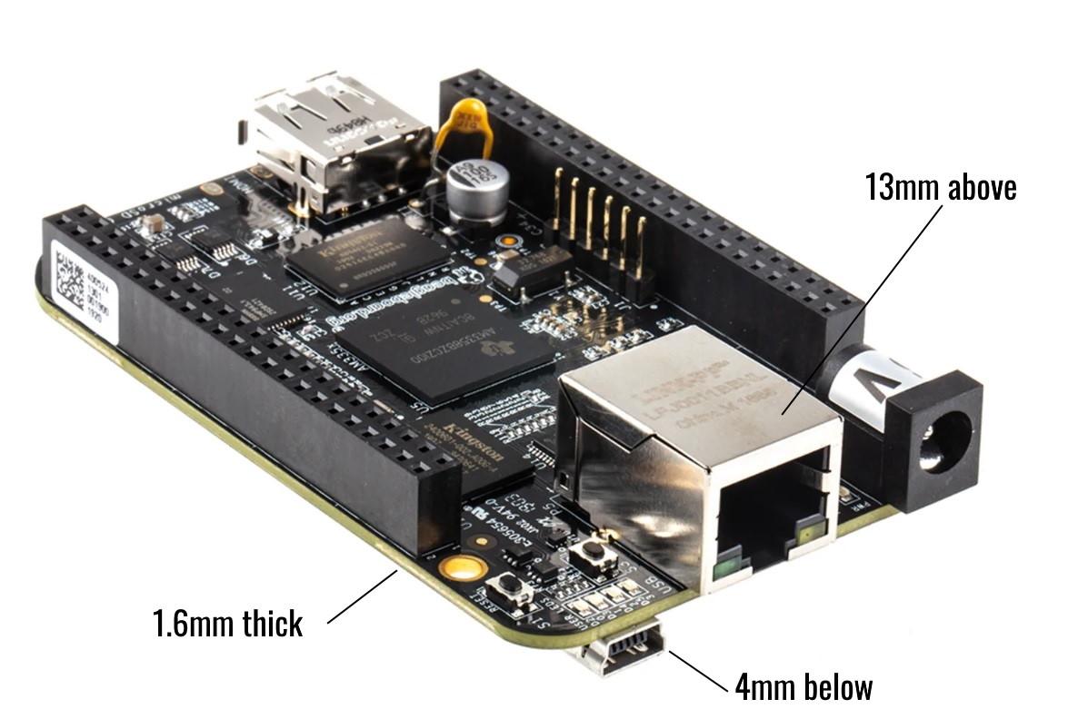
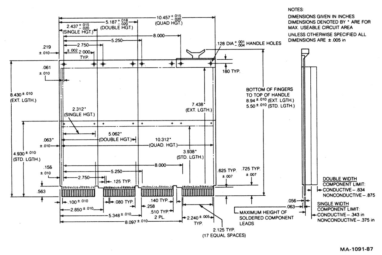
Per DEC's own specification for a Q-bus module, the maximum height a single-width board can rise above the top of the PCB is 8.71mm (.343") conductive / 9.52mm (.375") non-conductive, and drop 1.6mm (0.063") below the board, with a PCB thickness of 1.42mm (0.056").
Taken together, that means just the height of the Beaglebone's Ethernet RJ45 jack and the PCB are taller than the entire space available, not to mention the mini-USB jack on the underside of the board. This presents a problem for a densely stacked QBus enclosure.
By mounting the BeagleBone upside-down to its cape, the rise of the Ethernet jack becomes a drop below the UniBone/QBone. As most single-height boards do not rise to the maximum height available, the UniBone/QBone can "cheat" into this space for its DC barrel and Ethernet jacks in most configurations.
In the original UniBone design, Joerg connected the Beaglebone to the cape using ribbon cable and IDC headers. This allowed for some flexibility in moving the board up or down, depending on boards above and below. Unfortunately, this cable required custom manufacturing, a 3D printed adapter and mounting hardware was necessary, and the entire assembly experienced significant strain when installed or removed.
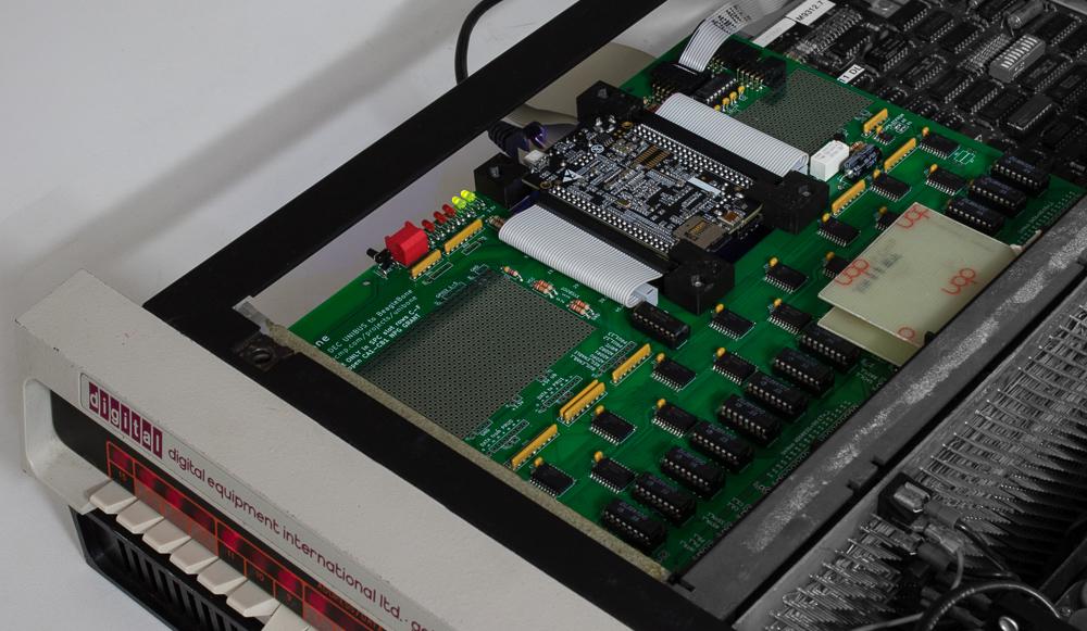
Rapidly, the ribbon cables were replaced by an interposer (or adapter) board. This second PCB mounts directly to the bottom of the UniBone/QBone. The BeagleBone directly connects to this second board. This makes for a more rigid structure, holding the BeagleBone at just about the best possible compromise between too-high and too-low. Only the topmost mini-USB jack must be protected from shorting against the board above the UniBone/QBone in the chassis. (For safety, we recommend protecting the entire BeagleBone top surface with insulating tape.
In Joerg's initial instructions, he recommends directly soldering the boards to each other, using "double length of solder and heating more than the double time." While this results in an electrically sound connection, it is not a very good physical connection. In testing, our first QBone exhibited a good electrical connection on the bench, but failed various bus driving tests intermittently, until the connection was reflowed. The problem recurred later after multiple insertions and removals.
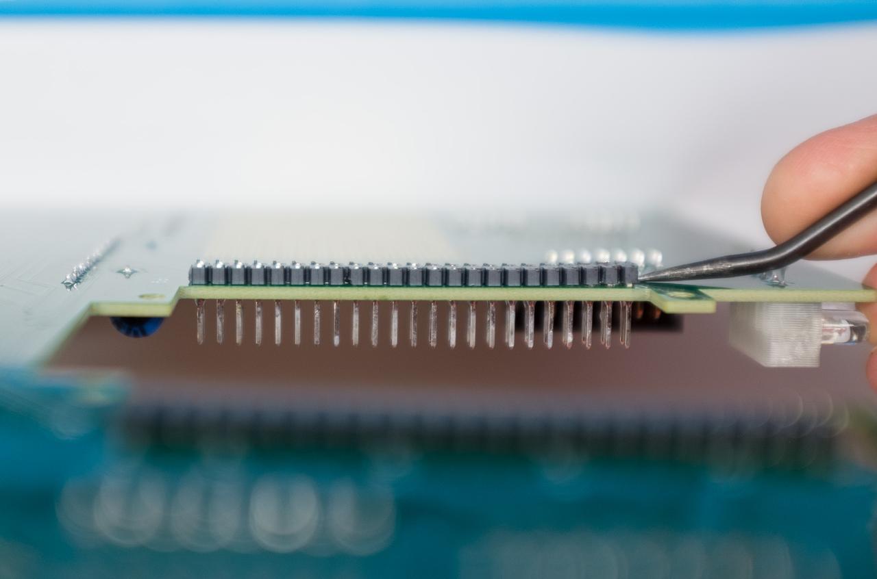
Soldering for electrical purposes makes both an electrical connection as well as makes a good physical connection. Solder, in this regard, is a bit like concrete: to make it stronger, you need to add internal reinforcement, especially to counteract perpendicular shearing and bending forces. In through-hole electronics, especially in areas where the board may flex or a connector may apply a torque, this rigidity is provided by the component leg.
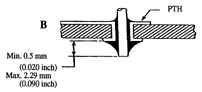
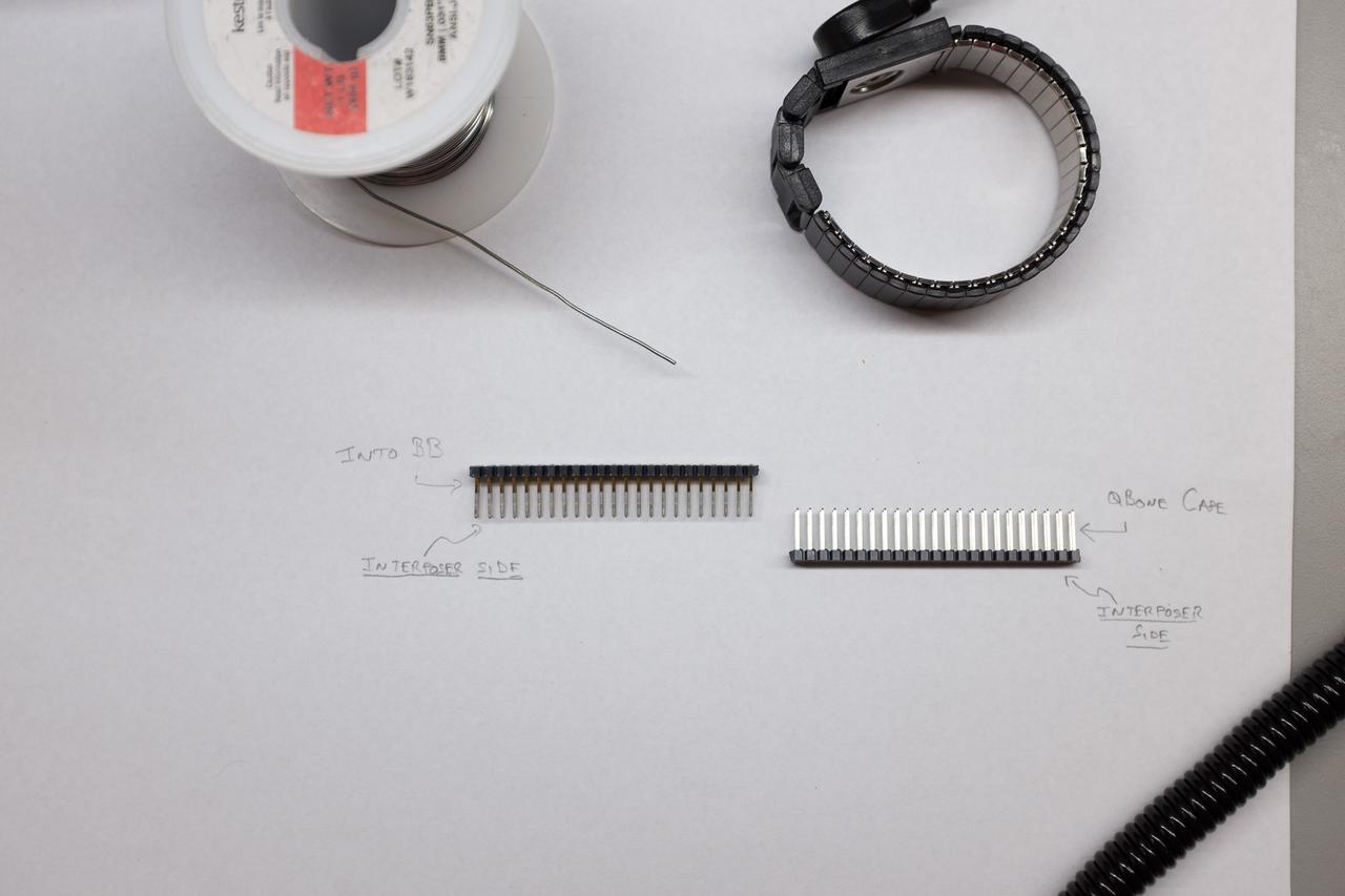
However, the bottom of the interposer board needs to be as flush as possible, to ensure maximal clearance with any boards below the UniBone/QBone in the rack. Similarly, the connector for the BeagleBone needs to be short enough that the BeagleBone can seat fully down against the interposer board. Otherwise, the UniBone/QBone will be too tall, and the BeagleBone's underside will contact the card above it in the rack. Also, these connectors must be trimmed to the right length, as stock parts are too long.
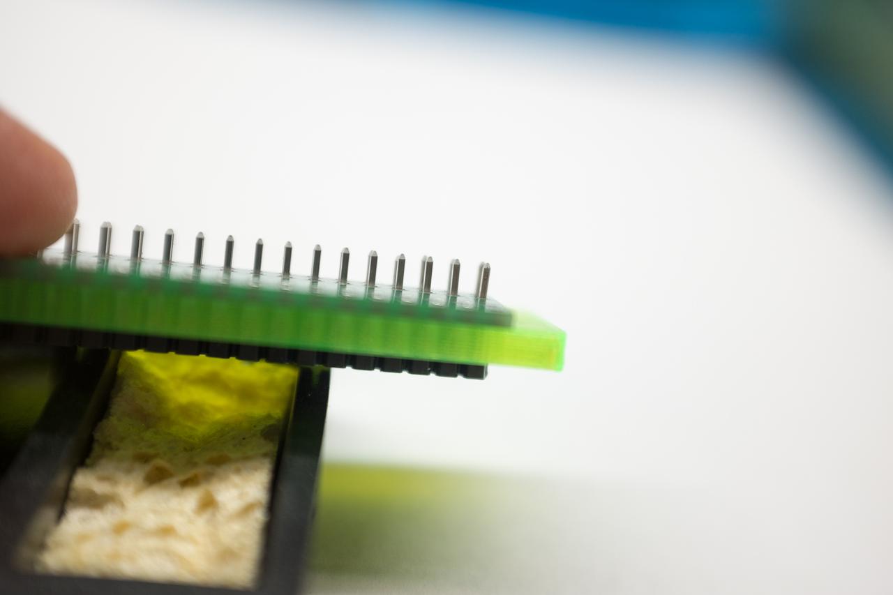
We solve all of the above issues by adding headers to the boards in both positions. For the BeagleBone's headers, we use a 3.5mm thick spacer (kits include this spacer!) to keep the pins the right length. This creates the perfect length of pin for the BeagleBone: it is a bit shorter than Joerg's original approach, but well within the specifications (pp. 95-96) for the connector. For the QBone side, a tin-only header is used to solder the boards together, and no spacer is required.
We've found this to be a more reliable electrical and physical connection, and we're confident this makes for a better kit building process.
Still confused? Here's our video of the assembly process.
Next time, we'll discuss the challenges of QBus driver ICs.