QBone Part 7: Yukon Gold
Some of you noticed the easter egg in our last blog post: the yellow QBone shown in the final image gallery.
Back when we first opened our web store, selling Snark Barkers, we received a common request: "are the edge connectors on these hard gold?" For the Snark Barker, and for the regular QBone, the answer is: no, they're ENIG.
ENIG deposits a very thin layer of gold via an immersion process over the top of the standard electroless nickel plating. The gold layer's thickness varies from 0.05 - 0.23 µm, over a 2.5 - 5.0 µm thick electroless nickel layer. We like ENIG for our boards, for many reasons:
Excellent resistance to oxidation
Low contact resistance and high strength
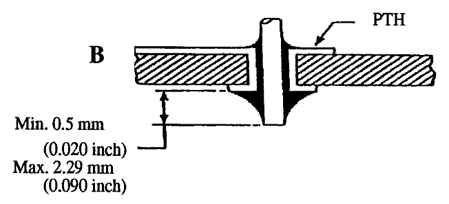
Good through-hole plating.
Surface finish is ideal for fine-pitch ICs, as it keeps the pads square-edged and flat.
ENIG handles reflow cycles well, a process we use to attach all of our SMD components
However, when applied to an edge connector, it is thin enough that repeated insertion/removal cycles can scrape off the gold.
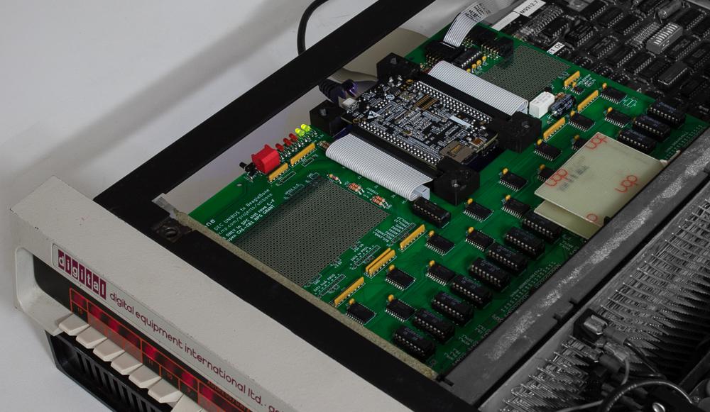
While we're confident that ENIG edge connectors are fine for at least 100 insertion/removal cycles, we know that some of you out there will want to use your QBone in many systems, or use them as diagnostic tools for other people's PDP-11 and VAX systems. (We also thought it'd be fun to make a premium QBone model.)
So we took the plunge and went all out with the QBone Yukon Gold edition!
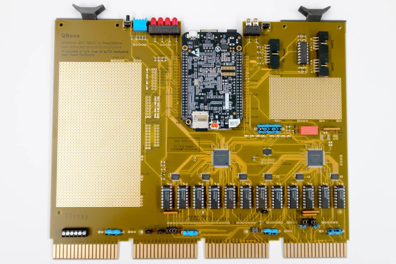
Presenting the QBone Yukon Gold, for the discerning vintage computer enthusiast.
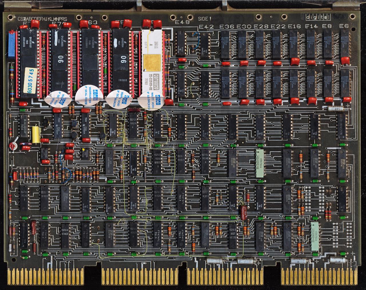
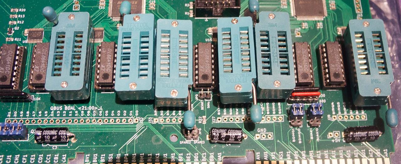
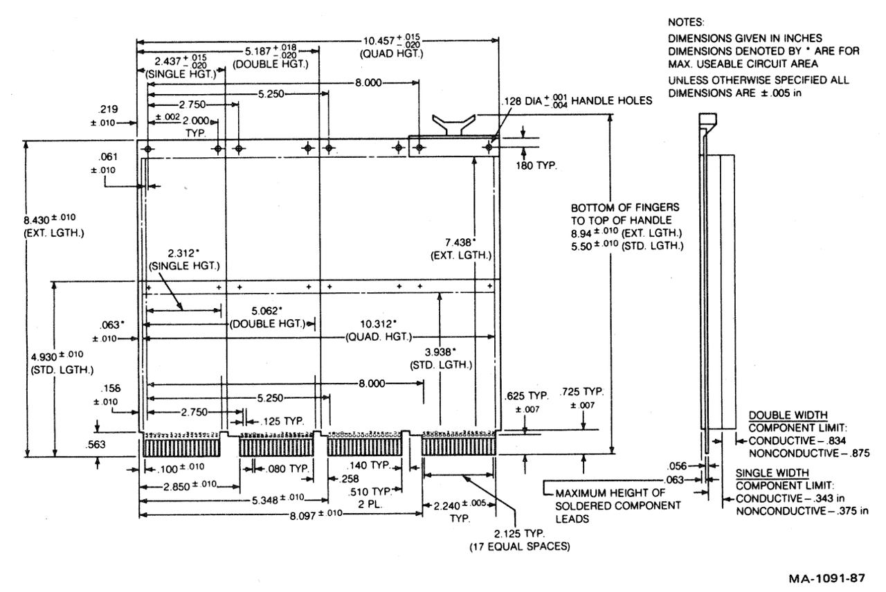
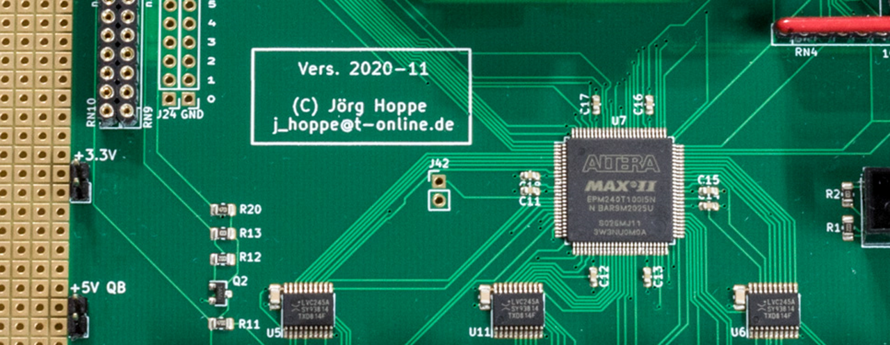
The Yukon Gold QBone sports true "hard gold" edge connector "gold fingers," at a thickness of at least 0.762 µm (30 microinch). This is comparable to most PCBs of the 1970s and 1980s, including DEC's own boards. We expect these fingers to last for thousands of insertion/removal cycles.
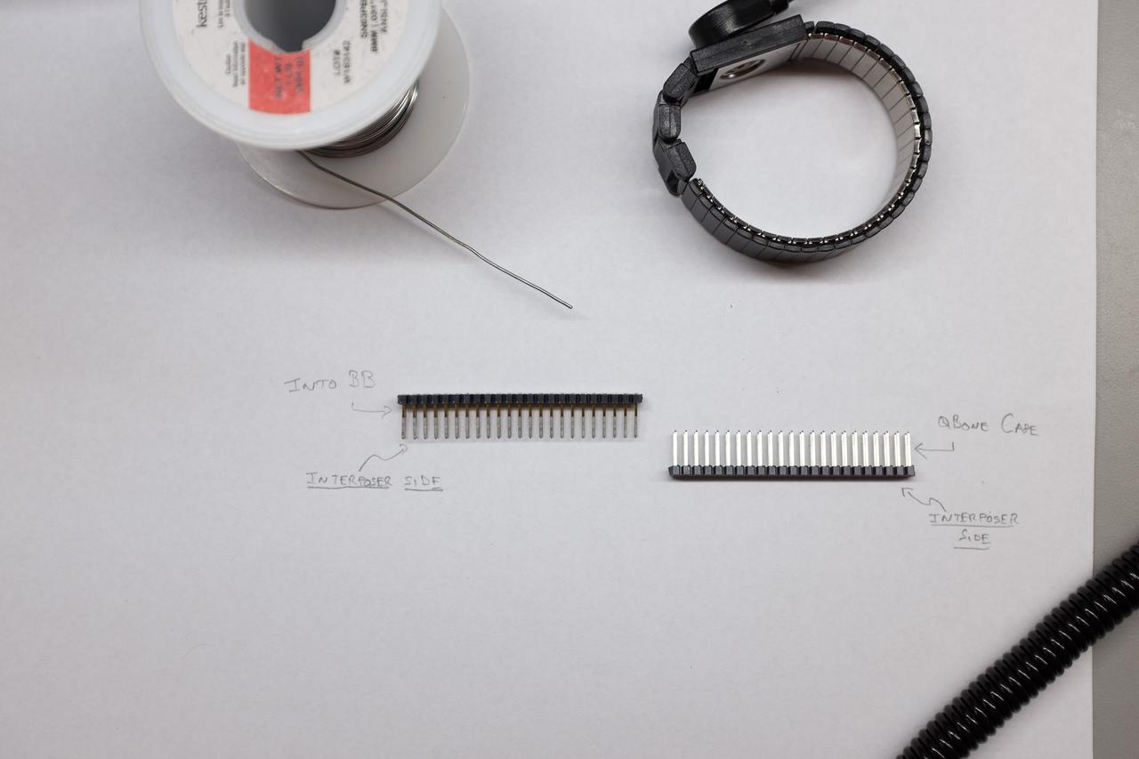
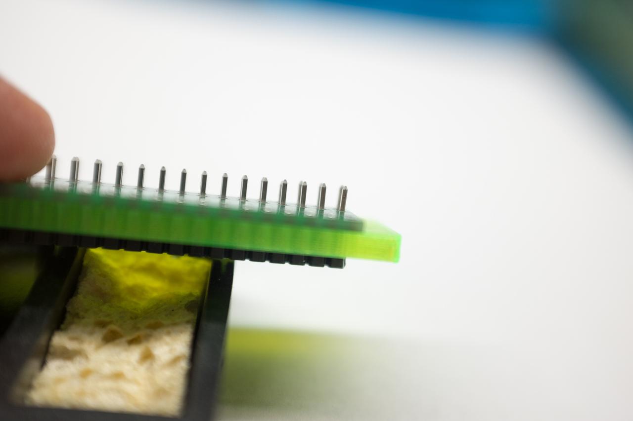
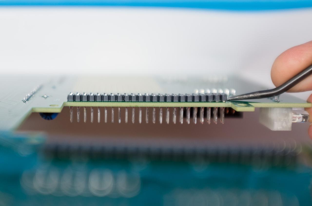
All pin headers and IC sockets in the Yukon Gold QBone also have 0.762 µm (30 microinch) plating.
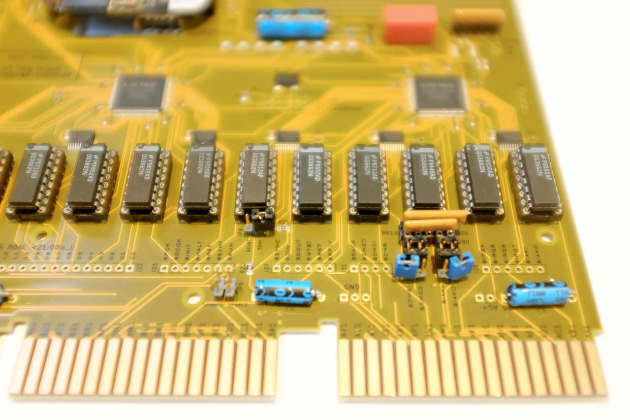
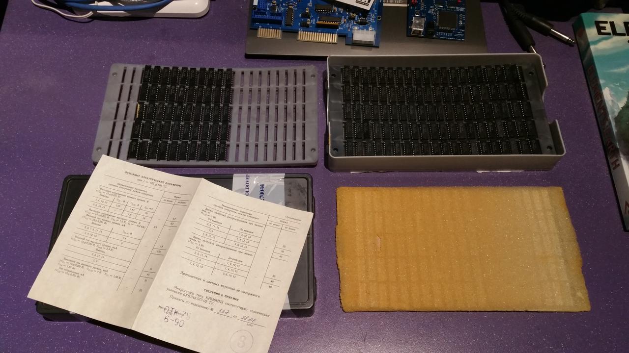
Each Yukon Gold QBone includes 12 fully-tested DS3662 driver chips, DEC's chosen upgraded QBus driver. All Yukon Gold QBones undergo a rigorous 24 hour burn-in test, to ensure these new old stock driver chips are fully functional.
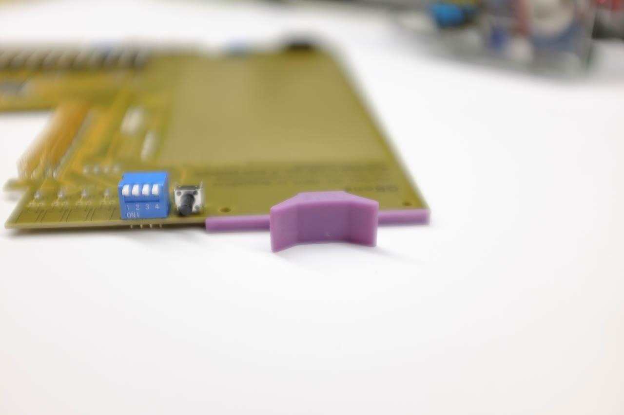
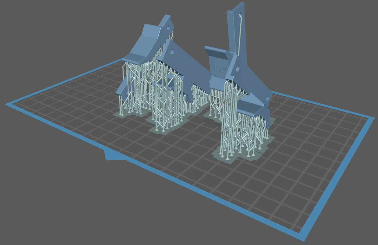
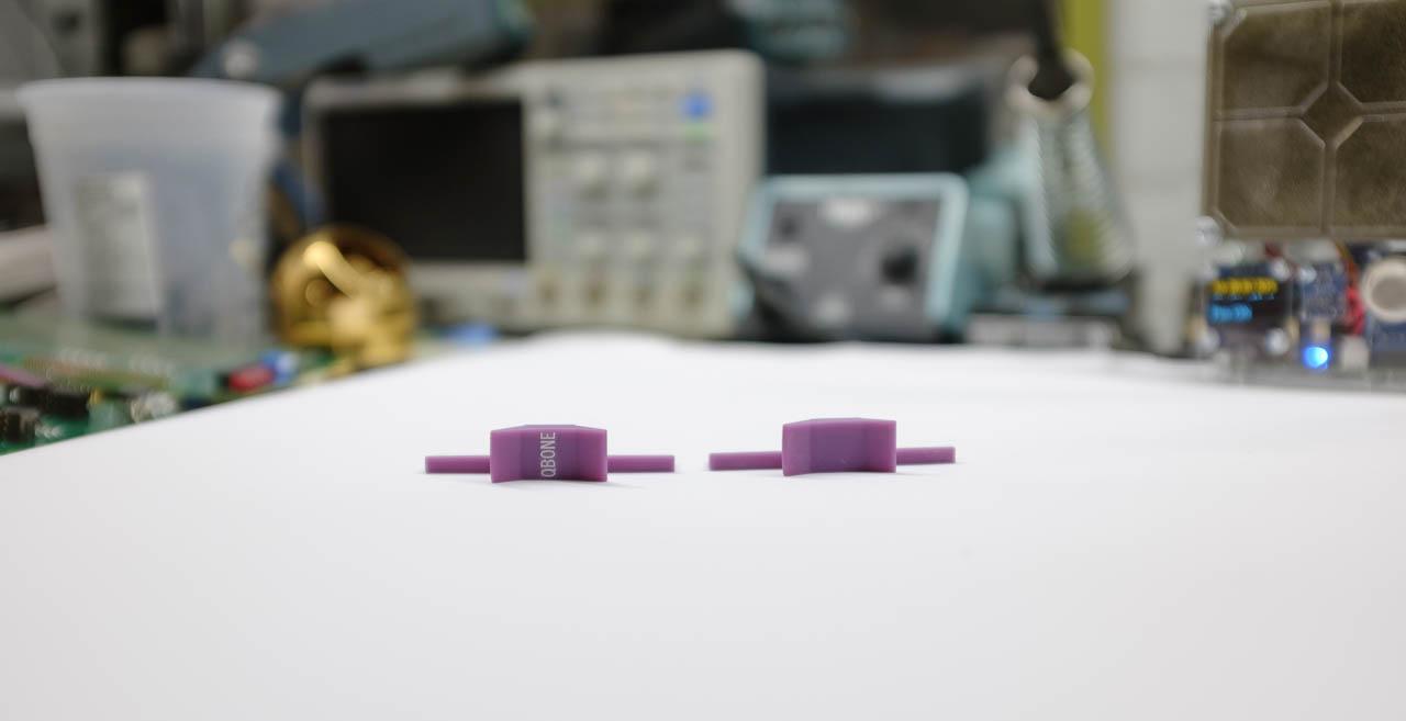
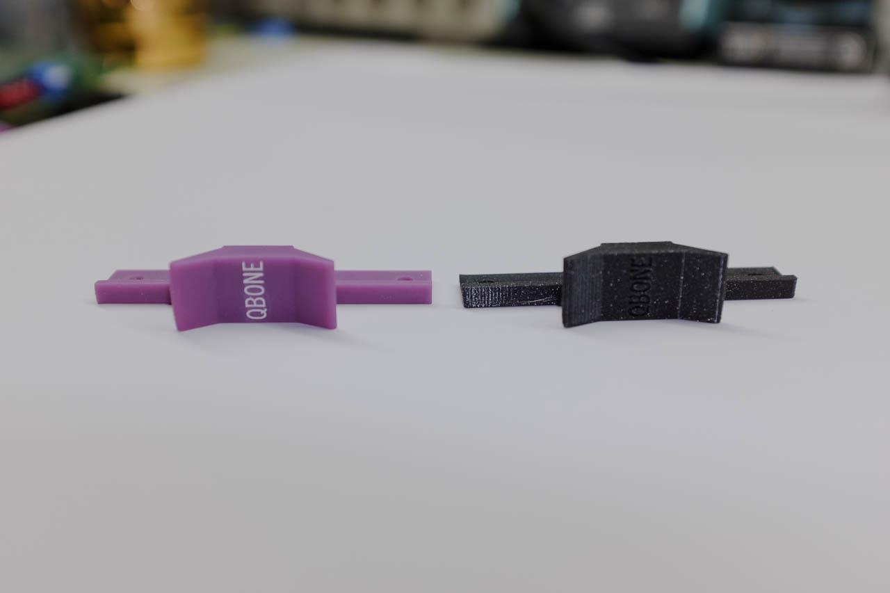
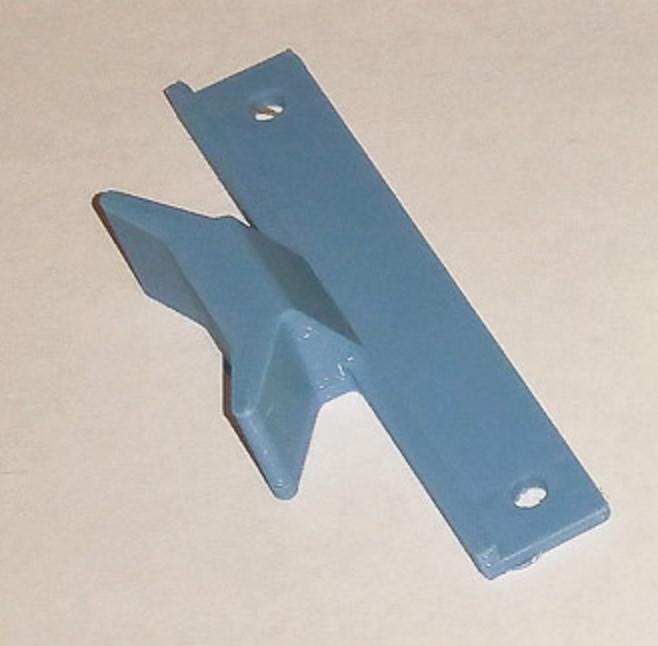
Finally, Yukon Gold QBones come with your choice of handle, including any of the premium FDM/FFF colours we offer, or the top-of-the-line resin printed handles. (That's why we don't show the handles in our pictures - your choice is riveted on before shipping.)
Due to the high cost of the gold and rarer driver chips in these units, we are offering just 10 Yukon Gold boards for sale. Once they're gone, they're gone!
Thanks for reading our QBone blog post series. We're now proud to offer both our standard QBone and the Yukon Gold edition for sale in our web shop.
